|
U-2R / TR-1 Wing Correction
Cutting Edge Modelworks
Previewed by David W. Aungst

HyperScale is proudly sponsored by Meteor
Productions
Cutting Edge is about to release three new update sets for the
late generation U-2. I made the masters for all three sets. I'll apologize
here up front for my enthusiasm about them. I am overjoyed with the way
the resin pieces came out and look forward to using them in my current
U-2S model. I'll try to keep the text objective here and let the pictures
of the pieces do the talking, but my enthusiasm will likely bubble
through.
I am only going to show the pieces at they come out of the set in this
review. Expect to see a built-up U-2S in the coming months on HyperScale
using all these sets.
This review is on the Wing Correction Set (CEC48441).
An Update
Set or a Correction Set?
|
This set is more than a simple update to the wing. It also corrects
some minor size issues with the wing control surfaces.
Before getting started with the creation of the flaps, I wanted to
determine the true details of the U-2 wing. Pictures I looked at showed
the details between that the flaps and ailerons were not captured quite
right on the kit. Further, the ailerons just seemed too big (long in span)
compared to the flaps. I decided the only way to be sure of all this was
to make a detailed comparison of the kit wing to known sizes on the real
aircraft.
On the rear cover of the Minigraph #28 book on the U-2R, there is an
engineer's drawing of the U-2R wing with all the design measurements
included. This seemed a good place to start for the camparison. I scanned
an image of the kit wing into my PC. Then, I scanned an image of this
diagram into my PC. Through a little foreplanning and some electronic
slight-of-hand, I got the images scaled to the same size and rotated to
nearly the same angle, then I super-imposed the diagram over the kit wing.
The following image was the result.
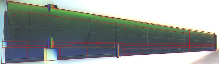
Wing Detail Comparison — Click the
Picture to View a Larger Image |
Several points are noted with close inspection of this image (click the
image to see the working copy I used for my actual analysis). Starting
from the wing root and moving outward:
-
The super pods are off by 1/8th
inch (a scale six inches). They are a little too close to the fuselage.
-
The span of the outboard wing flaps is not
long enough. This makes the break between the flaps and ailerons move
inboard 3/16th inch (a scale nine
inches).
-
The small non-moving section of the wing
between the flap and aileron is not represented in the kit at all. This
is the section where the fuel dump pipe is found. Acording to the
engineer's diagram, this section is six inches wide. This missing
section plus the shortened outboard flaps account for why I thought the
ailerons looked to long in span -- they are.
-
The aileron trim tab should not be as large
as the kit has it molded. It should be three feet, nine inches in span,
offset six inches from the inboard end of the aileron. The kit molds it
as five scale feet, flush with the inboard end of the aileron.
-
To make the aircraft easier to handle on
the ground, the outboard 70 inches of each wingtip can be folded. The
scribed lines for the fold on the kit are a scale foot too far inboard,
increasing the size of the folding wingtip.
-
Lastly, the wing cord at the tip is not
wide enough. This seems due to the leading edge of the kit having a very
slightly larger angle of sweep then it should while the trailing edge is
represented pretty close to where it belongs.
Before giving Italeri too much grief over these wing issues,
remember that this kit was created in the early 1980s when practically
everything about the U-2R was classified. The diagram I am using for my
comparison here was not published until many years after the kit was
released. That the details are as close as they are is actually a credit
to Italeri.
I wanted to create a wing update set to fix most all the inaccuracies
noted above -- all but one. The moving of the super pods six scale inches
(1/8th inch) outboard was something I
figured most modelers would not care about. If I had created the parts
with the super pods moved outboard, every modeler using this set would get
caught having to make the fix to where the super pod fairings are molded
onto the kit wing pieces. Hence, I chose to fix everthing else, but left
the super pod locations in place.
Industrious modelers that want absolute accuracy can easilly make some
small adjustments to the kit and resin pieces to move the super pods if
they like.
Creating the wing flaps was not difficult. They are simple flat slabs
with no curves to worry about. I cut 0.015" sheet styrene to the proper
sizes, then assembled them with liquid cement. I filled the seams after
assembly using super glue. I eyeballed the angle for how far to drop the
flaps, then added tabs to the leading edges that would insert into the
wings and hold the flaps at the proper angle.
I created the ailerons by starting with the kit pieces that I had cut
off my set of U-2 wings. I sanded these smooth and cut them to the correct
length. I added some styrene strip to the leading side of the pieces to
increase the aileron cord to the proper size. Then, I scribed in the trim
tabs and added the trim tab actuators to the lower sides.
I created the spoiler wells using a similar approach to what I did for
the wing flaps. The wells are basically long skinny boxes that I built
from sheet and strip strene. Once I had the sizes worked out, I added the
inide details like the various actuators. The most involving parts to
create were the tension springs for the spoiler actuators. They are thin
copper wire stolen from a broken electric motor, wrapped around a piece of
styrene round stock, then carefully measured and cut to length. All the
spoiler actuators have small 0.005" sheet styrene mold relief walls added
behind them so the pieces would be cast-able as single pieces.
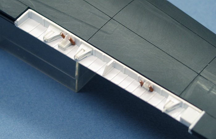
Completed Wing Spoiler Well |
The measurements provided on the engineer's drawing of the U-2 wing
provided me with the exact sizes for the GPS and System 20 fairings. I
created the GPS fairing with some Plastruct 3/16th
inch square stock, filling the center hole and filing the proper shape
into the ends. The System 20 fairing is Evergreen 3/16th
inch tube stock which I again filled the center hole and filed the proper
shape into the ends. Both fairings are integrally created with a small
(six scale inch) section of the wing that does not move. On this
non-moving wing section is found the fuel dump pipe for each wing.
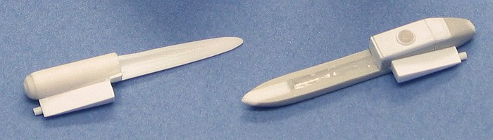
GPS and System 20 Fairings |
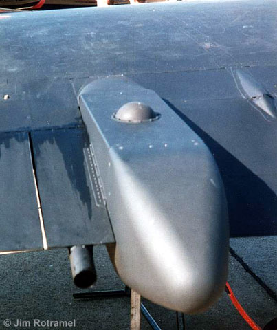
The final parts in the set are the scoops. Five cooling scoops are
found on the outboard sides of the two super pods (three on the left pod
and two on the right pod). Two other scoops of slightly different shape
are found, one under each wing. These are the fuel tank pressurization
scoops for pressurizing the wing fuel tanks in the event of needing to do
an emergency fuel dump.
The
Correction Set Described
|
The set is large and made up of twelve pieces, molded in the medium
gray resin that we have come to expect from Cutting Edge. There
were no molding imperfections in the test pieces sent to me.
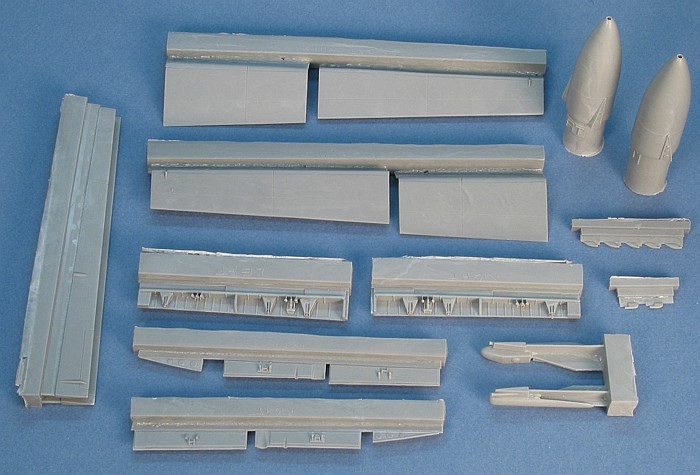
The Full Correction Set |
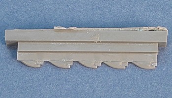
The flaps are broken down into inboard and outboard sections. Recessed
lines in the flap panels show the further separation of each panel into
two interconnected unit. The flaps are designed with tabs that extend into
the assembled wing halves and ensure the angle at which the flaps are
hanging.
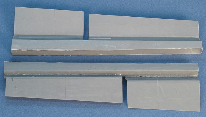
Wing Flaps |
Outboard of the flaps on each wing is an antenna fairing. The left side
is the GPS antenna. The right side is the System 20 antenna. The pieces
have the whole fairing represented, including the extended portions found
on the underside of the wings. Itegral with the antenna fairings is the
small non-moving portion of the wing trailing edge where the fuel dump
masts are located.
GPS and System 20 Antenna Fairings |
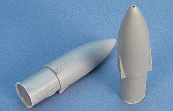
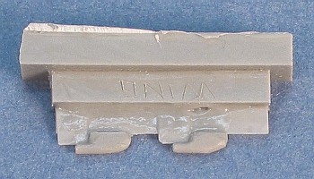
Super Pod Tail Cones |
The super pod tail cones are updated to include the aerodynamic
fairings that close the gaps between the pods and the wing flaps. They
also have the vent hole foud in their tips.
Next is the ailerons. They are molded with a portion of the aileron
actuator at their center. The trim tabs are scribed in the correct
location with their actuator fairing on the underside. The scribed line
near to the outboard end is the break point for the folding wingtip.
Ailerons |
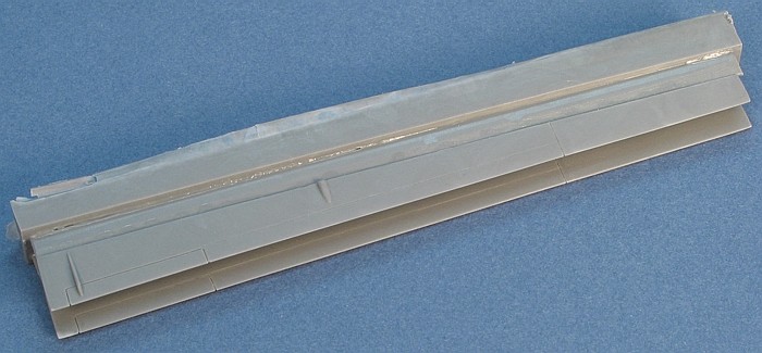
The last large pieces in the set are the wing spoilers. This is one of
those funky details that I wanted to include in the set, even though it is
extremely rare to see the spoilers raised on the ground. Instructions in
the set include details for using the set without raising the spoilers.
The two small triangular pieces next to the spoiler panels are facing
plates to detail the fuselage side that is exposed when the wing flaps are
lowered.

Spoiler Panels and Wells |
Rounding out the set is a series of tiny intake scoops. The group with
five scoops (the thinner looking ones) are for the outboard sides of the
super pods. Three scoops go on the left super pod; two go on the right
super pod. The group with only two scoops are the fuel tank pressurization
scoops. These mount under the wing, close to where the pogo legs are
attached. Note that the locations of the pogo legs in the kit are
incorrect and must be moved outboard almost three scale feet. The update
set instructions tell how far to move them.
Fuel Tank Pressurization Scoops |
Super Pod Scoops |
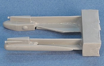
The following picture highlights the correction aspect of this set.
Besides the wing spoilers being enlarged and detailed, the break between
the wing flaps and ailerons was moved out. This is most evident by the
position of the System 20 fairing. Note also the non-moving portion of the
wing just outboard of the System 20 fairing and the corrected size of the
aileron trim tab.
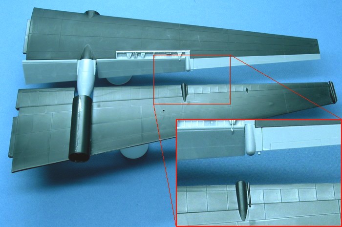
Wing Correction Details |
I wrote this review to show a little of what goes into the making of a
set of masters for a resin kit update. And, of course, I wrote this to
show off the new set. The castings caught every detail of my original
masters with great clarity. As the designer of the masters, I do not think
it is my place to recommend this set or not. I will let the pictures in
this posting speak for themselves and leave any recommendations to a more
objective reviewer.
As many people have noted, the list of statistics at the end of each of
my project postings makes me a true "bean counter". This posting would not
be complete without listing my time spent on the project. For the record,
on all three U-2R/S update sets collectively, I spent 86.2 hours (5.9 on
research, 80.3 on contruction). Very few models in my built collection
have reached this high a number of working hours. Wanting to build more
than just one U-2R/S (eventually), the time spent here will save me time
in having to scratch-build all these items for each U-2 model that I
build.
(Newest to Oldest)
-
U-2R/S Walk Around by David W Aungst
On-Line
HyperScale Reference, 2003
-
U-2: The Second Generation by Chris
Pocock
World Airpower Journal, Volume 28, AirTime Publishing, 1997
-
Dragon Lady by Ted Carlson /
Toyokazu Matsuzaki
Koku-Fan Magazine, Volume 1996-04, Bunrin-Do Company, Limited, 1996
-
Recce Tech by Paul F Crickmore
Osprey Color Series, Osprey Aerospace Publishing, 1989
-
U-2 Spyplane in Action by Larry
Davis
, Squadron In Action #86, Squadron Publishing, 1988/2002
-
Lockheed U-2R/TR-1 by Jay Miller
AeroFax MiniGraph #28, AeroFax, Inc., 1988
-
Lockheed U-2 by Jay Miller
AeroFax AeroGraph #3, AeroFax, Inc., 1983
Cutting Edge Modelworks products are
available online from Meteor Productions
website
Images and Information Copyright © 2003
David W. Aungst
This Page Created on 21 April, 2003
Last updated
14 August, 2003
Back to
HyperScale Main Page
Back to
Reviews Page |
 Home |
What's New |
Features |
Gallery |
Reviews |
Reference |
Forum |
Search
Home |
What's New |
Features |
Gallery |
Reviews |
Reference |
Forum |
Search