|
F-4/RF-4 Phantom II Intakes
Cutting Edge Modelworks 1/48
S u m m a r y
|
| Catalogue Number,
Description |
CEC48-455 -- the F-4B/C/D/N
with raised scribing (also the original F-4J)
CEC48-458 -- the F-4E/EJ/F/G with engraved scribing
CEC48-476 -- the F-4J/S and RF-4 with engraved scribing (yes,
different from the F-4E/EJ/F/G set)
CEC48-467 -- the British Phantom FG.1 and FGR.2 with engraved
scribing |
| Scale: |
1/48 |
| Contents and Media: |
See text and images |
| Price: |
each USD$19.99
available online from Meteor
Productions website |
| Review Type: |
FirstLook Review and Test
Fitting |
| Recommendation |
Highly Recommended |
Reviewed by David W. Aungst

HyperScale is proudly sponsored by Meteor
Productions
I have wanted some easy to use, seamless intakes for the Hasegawa
1/48th scale F-4 Phantom II kits ever
since they were released. Some manufactures have tried to provide these
over the years, but I was never happy with the amount of work required
to get them to fit into the kits. Cutting Edge has filled the
void, finally.
Dave Klaus at Meteor Productions (the parent company of the
Cutting Edge line) showed me the work in progress masters for the
Phantom intake sets last year. I was quite excited about what it would
mean for them to get finished. As time constraints would have it, Dave
was not getting the time he needed to work on the intakes, so early this
year, I offered to help. This gave me the perfect chance to make sure
that the intake sets were everything I wanted as I was going to be
completing them.
This posting reviews the intake sets as well as covering the
integration of the Cutting Edge intakes into a new Hasegawa
RF-4 kit (the RF-4EJ, to be specific).
Cutting
Edge's 1/48 scale F-4 Intake Sets Described
|
The Cutting Edge intake sets come packed in the now familar
black and yellow packaging, sealed inside a zip-lock baggie. There are
four sets available as follows.
-
CEC48-455 -- the F-4B/C/D/N
with raised scribing (also the original F-4J)
-
CEC48-458 -- the F-4E/EJ/F/G
with engraved scribing
-
CEC48-476 -- the F-4J/S and
RF-4 with engraved scribing (yes, different from the F-4E/EJ/F/G
set)
-
CEC48-467 -- the British
Phantom FG.1 and FGR.2 with engraved scribing
Be careful which kit you are buying intakes to fit into. If
you try to put the F-4E/EJ/F/G set onto an F-4S kit (for example), you
are in for some extra work to make them fit. Just to keep things
confusing, Hasegawa, in their infinite wisdom, has created four
unique intake set-ups that are not interchangable. This was a big
surprise to me, especially on the F-4E/EJ/F/G and F-4J/S kits.
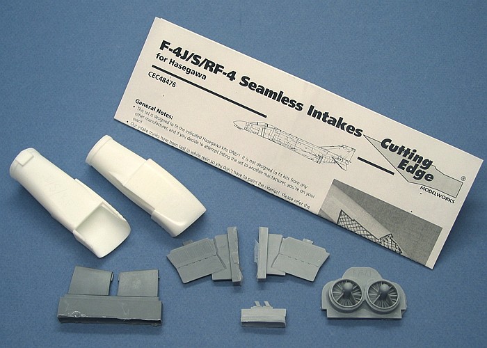
The baggie is packed full of resin. Most all the pieces in the set
are simple replacements of kit pieces. The bag contents include:
-
|
|

Click to Enlarge
|
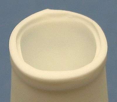
The main intake trunks. These are
molded in WHITE!!! It is not necessary to have to
paint the interiors on these.
-
The engine face bulkhead. This piece
differs between the J79 and Spey engine sets. Each set provides the
correct engine faces for the corresponding engine types.
-
The forward variable inlet ramps.
These are the inner intake pieces that go between the fuselage and
the intake trunk pieces.
-
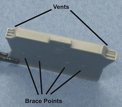
The intake splitter plates. These are
the formost pieces of the intake that split the unstable boundary
air along the fuselage away from the "clean" air going to the
intakes. Details provided on these pieces include the vents on the
upper and lower rear corners were the bleed air is vented out. There
are also four dimples on the back of the splitter plate to indicate
where the four braces are found for any modelers looking to add
these to their Phantom models.
-
The last items are the tiny pitots
found inside the intakes. These are sensors that tell the flight
computers how to set the geometry of the intakes at varying flight
attitudes and speeds.
The last item is a full notebook page size instruction sheet
providing information on how to use the intake set. Photophaphs and text
in the instructions clearly show where and how all the pieces go and how
much slag to remove from the backs of the intake trunks. There are also
two reference photographs of real Phantom intakes to assist in placing
the pitots into the intakes.
Installing
the Intake Set
|
The first step in the process is to verify that you have the correct
intake set for the model you are building. I will say it again -- these
sets will be trouble if you try to install the intake set into one of
the wrong versions of the model kits. With gobs of putty and lots of
sanding, the sets can be criss-crossed (if you insist on doing it), but
why make all that trouble for yourself? If the set matches the model,
the pieces are a drop-in fit, no different from if you used the kit
intake pieces.
Also, verify that the intake trunks and other pieces all agree to the
set you think they are. Of my review samples, I had one set (a British
intake set) where one of the intake trunks did not match. You want to
find this out before you start trying to use the intakes. I carved into
each set of intake trunks the versions it fits. The pieces on the sets
are very similar, and the white resin makes it difficult to see the
detailing. The people at Cutting Edge can easily cross pieces
without even knowing it. Double check your set before using it.
Assuming everything is alright, it is time to cut the fuselage as
shown in the instructions.
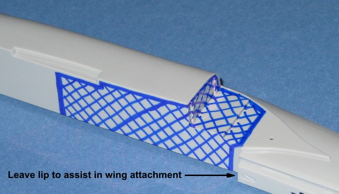
The wing pieces also need some minor cuts as shown.
When cleaning off the casting lugs from the back ends of the intake
trunks, take care. I am unsure what the cause is, but the inner lips are
not where they should be. I think it may be from mold stretching when
earlier pieces were pulled out. In any case, watch out for the lip on
the back. Of all the review samples I got, it was 50-50 on whether the
lip inside the trunk enough was far enough inside to survive cleaning
off the amount of casting plug that the instructions tell you to take
off. My advise is to check the inner lip first, then just level the back
ends of the trunks and leaving about a 1/16th
inch lip.
Some of my review samples had no lip due to the rough cut by
Cutting Edge already removing it. This is no big deal if you get a
set that has this issue. Simply use an X-acto knife to widen the back
ends of the trunks a little and they will slip onto the engine faces
without much trouble. The view from the front will be mostly the same,
no matter which way you install the engine faces.
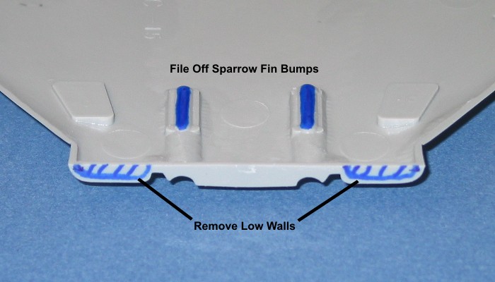
The intake splitter plates are provided to increase the detailing of
the kits intakes. While the part is basically the same as the
Hasegawa provided piece, the new splitter plate has the proper vents
on the trailing upper and lower corners. Also, small dimples mark the
locations of the bracing that exists on the real F-4 Phantom between the
splitter plate and fuselage (for modelers wanting to add this detail).
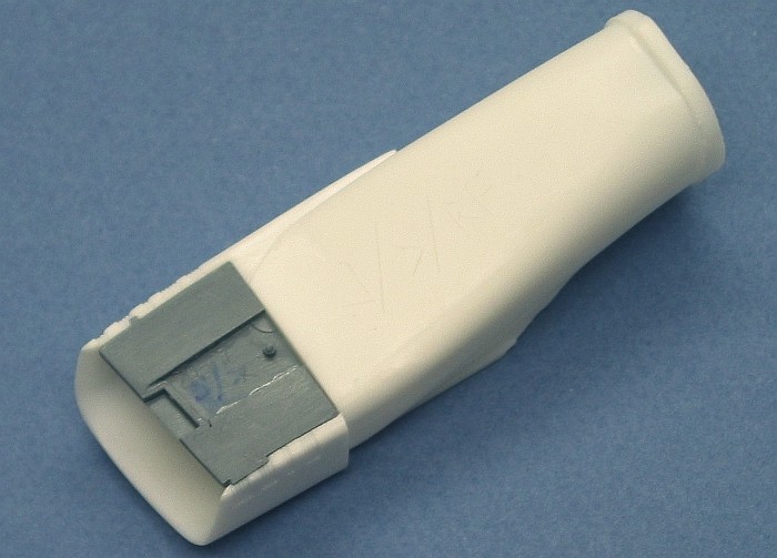
The inner variable intake ramps are provided as separate pieces for
two reasons. The first is that having the separate makes it easier to
paint the inner ducting areas (depending on the aircraft version). The
second reason is to facilitate attaching the intake pitots in place. The
picture below shows the assembled intake trunk, ready to be installed in
the fuselage.
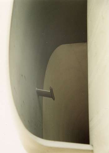
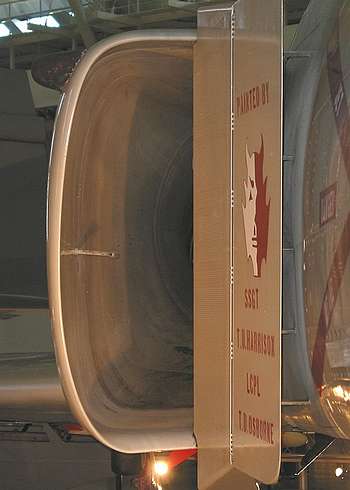
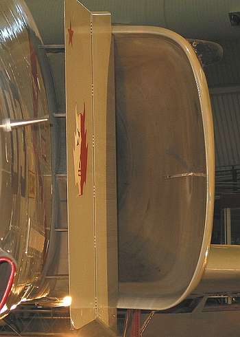
To assist in placing the pitots in the right place, I provided
Cutting Edge with some documentation images to include in their
instructions. I am also posting them here so they can be seen in color.
The top two were taken on two different RF-4C aircraft. The bottom two
were taken on the F-4S at the National Air and Space Museum Annex. There
are several points to note in these images.
-
The pitots are located just below the
half-way points up the intake outer sides. I made a drill point in
the masters to show the location of this. Unfortunately, I think I
needed to use a bigger drill bit. In about half the sets, the drill
point has nearly vanished during the casting process. If you hold
the intakes so that light shines across the outer area, you can
still find the dimple that my drill mark left. The other way to
locate the pitots is to know that the parallelagram panels on the
outside of the intake are the access panels to get to the pitot's
inner workings. You can use the location of these panels on the
outside of the intakes to assist in locating the pitots to the right
place on the inside of the intakes.
-
The pitots lean downwards at a
noticeable amount. Sorry, I did not climb in and measure the angle
(as much as I am wishing I had, now).
-
The entire inner variable ramp is
painted the camouflage color on Air Force aircraft. It is painted
white on Naval aircraft.
-
The outer intake walls are also
painted to match the camouflage on Air Force aircraft. The
measurement of the camouflaged section (so I have been told) is
three feet. This area is left white in naval aircraft.
-
Note the dirty rear portion of the
intake duct for the image that shows the engine face. This is fairly
typical of most all jets I have had the chance to look into their
intakes. They seem to get dirtier the closer to the engine face you
get.
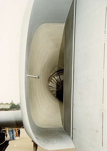
Real Phantom Intake |
Real Phantom Intake |
Real Phantom Intake |
Real Phantom Intake |
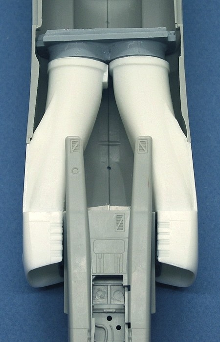
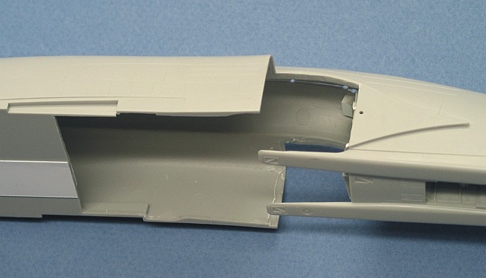
This is a final view of the fuselage with the intakes in place. This
looks just like the image of the masters that I posted about a month
ago, except that now they are white.
On playing with the pieces, I am tossed up on the installation order.
When I wrote the instructions, I thought that getting the rear engine
bulkhead glued into place first would help in getting everything solid.
After some play with the actual resin parts, I am now thinking that the
intake trunks fit solid enough without the engine face. Thus, I am
leaning on the idea that the trunks should be attached solidly, first.
Then, after that, attach the engine faces to the rear sections.
Either assembly order will work. I guess it is really up to the
modeler's personal preference.
Conclusions
Man! Am I ready now or what? This has been the last big item I needed
to get in order to start building the eighty or so Hasegawa
Phantom kits sitting in my stockpile. Armed with these intakes and all
the other goodies that have slowly been coming out over the past few
years, I now have very little reason to not build Phantoms the way I
always have wanted
Highly Recommended.
Cutting Edge Modelworks products are
available online from Meteor Productions
website
Images and Information Copyright © 2004
David W. Aungst
This Page Created on 21 April, 2004
Last updated
21 April, 2004
Back to
HyperScale Main Page
Back to
Reviews Page |
 Home |
What's New |
Features |
Gallery |
Reviews |
Reference |
Forum |
Search
Home |
What's New |
Features |
Gallery |
Reviews |
Reference |
Forum |
Search