CT-114 Tutor Upgrade Set
Uncle Bill's Hobbies, 1/48 scale
S u m
m a r y
|
|
Catalogue Number: |
Uncle Bill's
Hobbies - CT-115 Tutor Upgrade Kit |
|
Price: |
Available
online from Uncle Bill's Hobbies |
|
Scale: |
1/48 |
|
Contents and Media: |
47
Resin parts cast in grey resin plus 2 vacform |
|
Review Type: |
First Look |
|
Advantages: |
Much needed item – completely replaces cockpit plus parts
for speed brakes, light housing, flaps and nose wheel; big improvement over kit parts;
good
detail, well cast; accurate. |
|
Disadvantages: |
Instructions could
be better |
|
Recommendation: |
Highly Recommended |

HyperScale is proudly sponsored by Squadron.com
Reviewed by
Tom Sime
Background
First flown in 1961 and introduced into Canadian service in the 1964
with the final aircraft being delivered in 1967, the Canadair CT-114
Tutor has now been in service with the Canadian Air Force for over 40
years. Much of this time was in the role as a trainer for basic and
advanced pilot training until it was replaced by the CT-156 Harvard II
and CT-155 Hawk in 2000. No longer used in a training role, the Tutor
still continues in service to the Aerospace Engineering Test
Establishment. as well as with the CAF aerobatic team “The Snowbirds”
with whom it has been in service since 1971.
Base Kit
This resin kit is designed for use with the Hobbycraft 1/48 scale
Tutor which is available in two version: the “ ‘ Military’ Tutor” and
the “Tutor ‘Snowbirds’”. Parts and instructions for both boxing’s of
this kit are basically identical, the only difference between them being
the decal sheet. The “Military” Tutor has decals for 4 aircraft: these
include 2 Canadian Machines (an early1965 and a late 1995 Tutor) and 2
Malaysian Tutors (one in early markings 1967 and a late version 1985).
The Tutor “Snowbirds” has sufficient numbers to do any of the
Snowbird aircraft. Since its release, this somewhat basic kit has been
crying out for an improvement set to address its numerous shortcomings:
the “CT-114 Tutor Upgrade Set” goes a long way in doing this.
CT-114 Tutor Upgrade Set
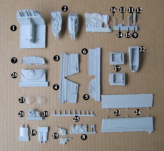
Mastered by the talented Wayne Hui, this resin kit contains 47 finely
detailed and 2 vacuum formed parts resin - see the image above you’ll
find that for the sake of clarity I have numbered the castings to
correspond with kit’s parts list. Wayne’s fine pattern making ensures
the fit, finish and detail of the parts are first rate throughout.
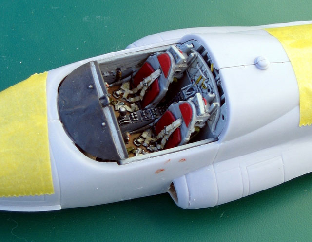
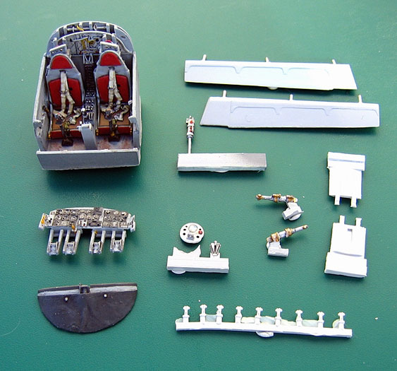
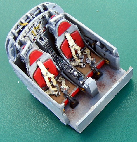
The kit includes 26 parts that make up a much improved cockpit with
additional parts that including a new nose light housing with a clear
vacuum formed late model beak shaped cover (two of these are
included-just in case) as well as 6 parts for the speed brakes. You’ll
also find inside two new flaps with actuator connectors totaling 11
resin parts this includes 3 spare actuators, as these are very small and
delicate. The inclusion of spares is a great idea that other
manufacturers should feel free to mimic. Finally this is all rounded-off
with a new nose wheel well. Complementing Wayne’s work in creating the
masters is mold maker and cast master Steven Sakulic of IFactory. Steven
has done remarkable work both in preparing the molds and casting this
kit. IFactory is a small company and it doesn’t have access to the same
high tech equipment that the major manufacturers use. As a result of
this you can expect some flash on some of the smaller parts; larger
parts are flash free and clean up with a few light strokes of a sanding
stick. Steven’s attention to detail has resulted in castings that are
sharp, clean and completely bubble- free, with pour blocks that are
commendably small and can easily be removed in seconds using a number 11
blade. The overall quality of this kit compares very favorably with the
current range of similar products from the “big boys” and stands as a
testament as to what can be achieved by a committed skilled individual.
I found the only real weak point to this kit is the instructions. These
are printed on standard A4 format paper, could have been clearer and the
diagrams would have benefited from being larger. Parts 16 handles X2 are
not illustrated however there are location holes for them outboard of
the ejection seats between the seats and the cockpit walls. The landing
gear handles parts number11 location points are not clearly defined.
These parts should each be located at the bottom end of two keyhole
shaped “slots”; you’ll find one of these on the small panel that is at
the front of and to the starboard side of the centre console and the
other goes on the inboard angled part on the portside of the main
instrument panel. The inertia real control levers-the two small handles
with the round balls on the end- fit into the top of the raised box that
sits on the upper edge on the left side frame of each seat where it
transitions from seat to backrest. You will only require one canopy
actuator (part 9) but will find castings of two: spares never go wrong!
Assembly started in the usual manner, with a clean up of parts. First
I removed the small membrane of flash that you’ll find on some of the
fine delicate parts. Ironically, the flash which is traditional regarded
as a nuisance helps to prevent these parts from damage/breakage during
transportation/postage. You can make flash serve a very positive purpose
to help facilitate clean up the mold lines on smaller parts, which I
always find a fiddly task. I have found that to clean the small
parts-and some of these kit parts are indeed very small parts-the best
way is to remove the flash from along one side and above the part with
the tip of a new number 11 blade. When doing this the flash on the
opposing side of the part will help support the part and make cleaning
of that side easier. Once you are happy with the one side take a small
piece if masking tape and attach this to the cleaned-up side and to the
poring block: this will help to brace the part during clean- up as well
as reduce the “sproing factor”. In the unlikely event that a part does
in fact “sproing” then there is a good chance that-being stuck to the
tape- it won’t go far. If it does fly, it will take the tape with it-
making it easier to find after launch and so solving the age old problem
of rug burn to the nose as you search for those little thingamabobs!
Pour blocks are minimal and the only pour blocks that required the use
of a saw where those on the ejection seat, these are extremely small and
it’s the work of only a few moments to remove them. Unlike the castings
of some of the major manufacturers of resin kits, with IFactory you
don’t end up with more resin in poring blocks than you do parts.
Assembly started as per the kit instructions and follows the “usual”
assembly sequence for building a tub, ie: glue cockpit side panels to
fuselage interior, build/detail floor and seats etc. However, after I’d
glued the side panels on, I quickly changed my mind on this and I
decided that the “Tutor upgrade set” deserved a better Tutor! I
therefore decided to upgrade the Hobbycraft parts and to scribe the
panel lines and bring the rest of the kit up to the standard of the
cockpit set. Off came the side panels and I assembled the tub as a
separate entity so that it can be fitted to the plastic once those parts
have been brought up to a higher standard.
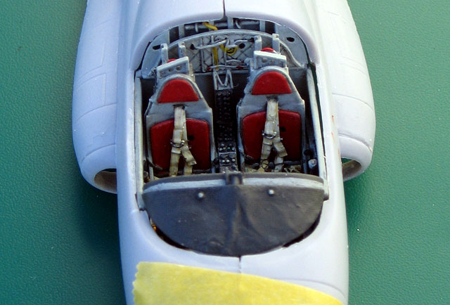
The cockpit side-walls were attached to the floor after a few strokes
with a sanding stick along the sides of them to remove the finest of
mold lines. These are wonderfully thin parts. The fabric quilted panels
on the cockpit sides and on the rear bulkhead are faithfully reproduced.
The kit’s cockpit floor has obviously been the base for the master
pattern for the new floor, as the kit part lacks detail but is a very
good fit then this made a good foundation for the master pattern.
However there are a couple of ejector pin marks on this that have been
carried over on the master and these require a light sanding to remove
them. The distinctive shape of the Tutors ejection seats have been
faithfully captured and include separate inertia real control lever
handles and separate canopy breakers. It should however be noted that
the canopy breakers are left and right- handed, with their highest point
being to the centre line of the cockpit. The canopy breakers have three
lightening points in them and on the kit castings these are represented
as round recesses, I opted to drill these out. The main instrument panel
paints up well and looks good oob, I did however use Mike Grant’s decals
to further enhance instrumentation as well as adding two more handles.
These are the ones painted in yellow as these were present in almost all
of the images of Tutor instruments panels that I could find. I broke the
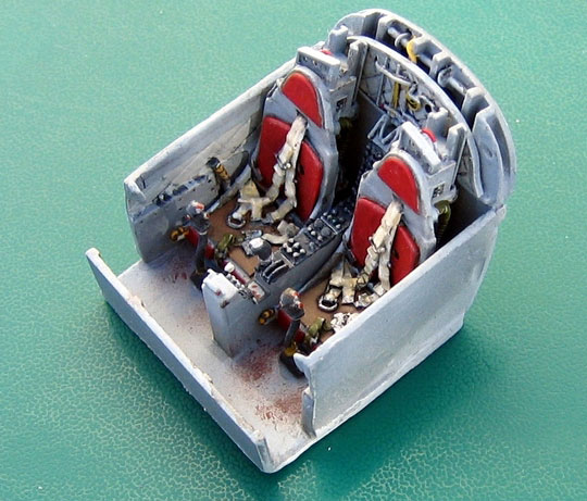
work on the cockpit down into five sub- assemblies: tub, seats,
instrument panel, instrument panel cover and finally the levers handles
and actuators which I left on their pore blocks. I then painted these
separately after painting the major components I then added the pre-
painted small levers and handles and completed the cockpit assembly.
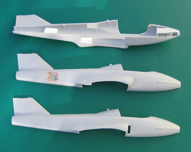
Between painting stages, I worked on the nose wheel bay, the speed
brakes and the flaps. The nose wheel bay was the only part that I found
to be difficult to install. Installation requires the removal of the
kits cast wheel wells and of a mass of soft thick Hobbycraft plastic
from the inside of the lower fuselage wall. After this has been done,
you have two choices; the front of the resin part extends below its
sides and this either has to be trimmed back to fit inside the fuselage
or you must extend the wheel well opening forward then fill and sand
this part to conform to the nose shape. The latter method became my
“method of choice” when- in an overenthusiastic moment- my Mini Dremel
punctured the plastic in this area. The installation of the speed brakes
requires the removal of the cast on closed Hobbycraft speed brake doors.
This was done scoring over the Hobbycraft engraved panel lines scoring
along all four sides until the doors popped out then the engraved hinges
were removed in the same way. The new resin speed brake wells walls are
very thin and this helps make their insertion into this opening an easy
task.
In addition to the wells, you also get new speed brakes and actuators
for them. With the flaps, I once again deviated from instructions and
instead of removing the kit parts and extending and reshaping the area
where the flaps attach, I opted to handle this in another way.
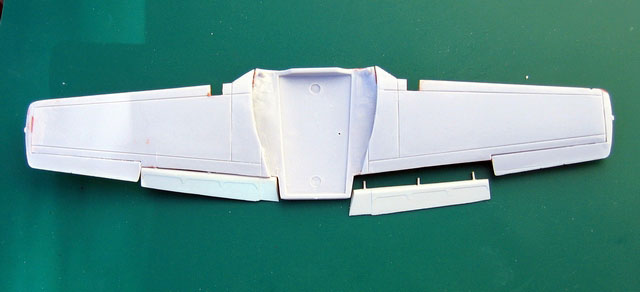
I cemented the wing halves together and once the cement had set, I
removed the kits flaps and- using a rasp- I reshaped the exposed hinge
area to the profile of the flaps hinge face. I then drilled holes in
each wing to take the new flaps as I wasn’t sure that the three thin
locating pins cast on the resin flaps would be strong enough ergo I
replaced these with brass rods. As the flaps extend under the fuselage
then when the flaps are in the lowered position it is possible it look
into the fuselage, I therefore boxed this area in.
Click the thumbnails below
to view larger images:
Snowbirds
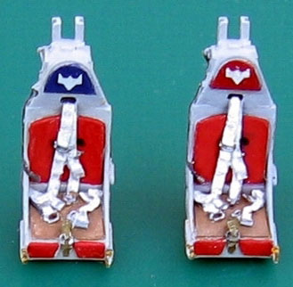
If you decide to do your Tutor as a Snowbird it should be noted that
Snowbird aircraft headrest are different from the standard pattern.
Snowbirds planes have one red and one blue headrest and these are
emblazoned with a white Snowbird emblem. All odd numbered Snowbirds have
the red seat on the port side of the cockpit and even number birds have
their red seat on the starboard side. The reason for this is that odd
number birds fly to the leaders starboard and even numbers to the team
leader’s port side. By alternating the pilots port and starboard when in
formation each pilot is positioned to the centre of the formation and
this helps them to maintain a tight group.
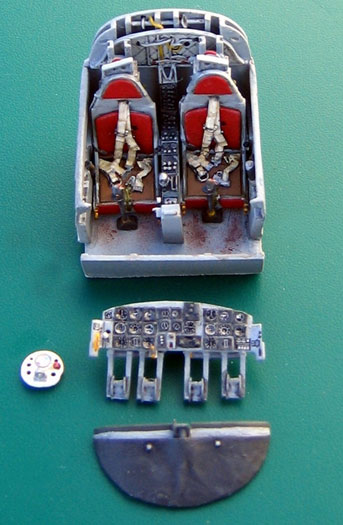
Decals
The instructions recommend the use of Mike Grant instrument decals to
finish off the instrument panel .I have wanted to try these decals for
some time and decided that this would be a good opportunity to do so. An
email to Mike Grant resulted in me taking delivery of 4 sets of his
exquisite decals: 2 in 1/72 for the smaller dials and 2 in 1/48 for the
larger dials. One of the reasons that I hadn’t tried these decals before
is that I don’t own a punch and dye set and popular opinion seemed to
imply that this was a “necessity” for the removal of the decals from
their backing. I pondered this for a time and came up with the following
inexpensive solution that worked well for me. Taking some small diameter
brass tube, I sanded the outer walls towards the centre until I had a
sharp edge. I then used a reefer file on the inside of the tube and this
gives the brass tube a nice knife- edge. I cut the tube into a 1 ½”
section and inserted this into a 3” length of dowel. I now had a punch
tool that when positioned over the decal and given a short sharp tap
with a hammer cut a perfect circle.
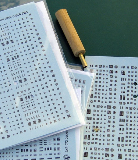
I applied the decals to my resin instrument panel and was pleased
with the results-this quickly changed to delight when I added a spot of
Future to each of the dials and the detail just popped out.
The Calgary Connection
This build has had a very distinctive and unusual connection in that
everyone involved with the Tutor upgrade set, the decals and the build
are all from Calgary Alberta:
Rick Chin is the proprietor of Uncle Bills Hobbies and the source for
this kit.
http://members.shaw.ca/unclebills/
Wayne Hui –master pattern maker
http://www.modelart.ca/
Steven Sakulic of IFactory: independent mold and cast master.
resinbox@shaw.ca
Mike Grant of Mike Grant Decals: graphic artist.
http://www.mikegrantdecals.com/
Tom Sime: model-builder and reviewer.
Review and Images Copyright © 2006 by Tom
Sime
Page Created 22 May, 2006
Last updated 21 May, 2006
Back to HyperScale
Main Page
Back to Reviews Page
|
 Home |
What's New |
Features |
Gallery |
Reviews |
Reference |
Forum |
Search
Home |
What's New |
Features |
Gallery |
Reviews |
Reference |
Forum |
Search